
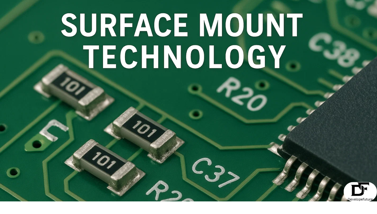
Surface Mount Technology (SMT) is one of the most revolutionary advancements in the electronics industry. Surface Mount Technology is a method of producing electronic circuits. In which the components are mounted directly. Onto the surface of printed circuit boards (PCBs). Unlike traditional through-hole technology. This requires inserting component leads into drilled holes. Surface Mount Technology enables the use of smaller components. It has faster assembly and higher circuit density. This makes SMT the backbone of modern electronics manufacturing.
The importance of SMT cannot be overstated in today’s world of compact. and it is a high-performance device. From smartphones and laptops to medical instruments and automotive electronics, SMT has enabled miniaturization. While it maintains functionality. Its efficiency has not only transformed how devices are manufactured. But also how engineers design and test circuits.
Here we’ll explore the history, applications, benefits, challenges, and design aspects of Surface Mount Technology. We’ll also discuss its comparison with through-hole technology. The tools used in assembly, soldering techniques, and the standards. That govern its implementation. You’ll have a complete understanding of how SMT continues to shape the future of electronics manufacturing.
Table of Contents
The Development of Surface Mount Technology (SMT)
Surface Mount Technology emerged in the 1960s and gained traction in the 1980s. As consumer electronics demanded smaller and more efficient designs. Initially, through-hole technology dominated the market. But as devices required higher component density. Surface Mount Technology became the preferred method. Companies like IBM and Philips were among the first to adopt it. For the use of advanced computing systems.
Over the decades, SMT has evolved with innovations in soldering techniques. Its automated assembly machinery, and miniaturized components. Today, Surface Mount Technology is considered the industry standard. Continuous research ensures SMT remains adaptable to new demands. Such as flexible electronics, Internet of Things (IoT) devices, and energy-efficient systems.
Differences Between Through-Hole Technology and Surface Mount Technology
Through-hole technology involves drilling holes into the PCB and inserting leads of components. Which are then soldered on the opposite side. This method provides strong mechanical bonds. It is making ideal for components. That experience physical stress such as connectors or large transformers.
Surface Mount Technology attaches components directly to the PCB’s surface using solder paste. This allows for more compact circuits and double-sided assemblies. While SMT offers speed and efficiency. Through-hole remains useful in applications that need durability and structural strength.
Factors to Consider When Choosing SMT or Through-Hole Technology
When deciding between SMT and through-hole technology, engineers must evaluate project requirements. If the design demands compactness, lightweight assemblies, and high-speed production, SMT is usually preferred. It is especially beneficial for high-volume manufacturing.
Through-hole technology may be the better choice for prototyping, repairability. Or when dealing with components exposed to mechanical stress. Hybrid PCBs, which incorporate both SMT and through-hole elements. These are often used to balance advantages from both approaches.
Pros and Cons of Surface Mount Technology
Pros
SMT offers several advantages, the most notable being miniaturization. With smaller components and tighter placements, devices can be more compact. While still supporting advanced functionalities. It also enables higher-speed manufacturing. Since it automated machines can place components at rapid rates.
Another benefit is the ability to mount components on both sides of the PCB. Significantly it is increasing circuit density. Cost reduction is also a strong advantage. Surface Mount Technology reduces material usage, drilling costs, and manual labor in assembly.
Cons
Despite its strengths, Surface Mount Technology has limitations. Repair and rework of SMT assemblies can be challenging. Due to the small size of components and their high density on boards. Specialized equipment is often required for inspection and repair.
Components mounted with SMT are generally less mechanically robust compared to through-hole counterparts. This makes them unsuitable for high-stress applications unless reinforced with design adjustments. Temperature sensitivity during soldering is another challenge engineers must address.
Soldering Techniques in Surface Mount Technology
Soldering is the backbone of SMT assembly. The most common technique is reflow soldering where solder paste is applied to pads. Components are placed, and the assembly is heated to melt and solidify the solder.
Another method is wave soldering. Which is less common for SMT but still used in mixed-technology boards. For precise repairs or small-scale production, hand soldering with fine-tipped soldering irons is employed. Automated soldering techniques ensure consistency, reliability, and minimal defects in mass production.

Types of Surface Mount Device Packages
SMT devices come in various packages tailored for specific applications. Chip resistors and capacitors are among the most common, offering standardized sizes. Small Outline Integrated Circuits (SOICs) provide compact solutions for ICs.
Other examples include Quad Flat Packages (QFPs), Ball Grid Arrays (BGAs), and Chip-Scale Packages (CSPs). Each package type has unique advantages. Such as improved heat dissipation or increased pin density. It is making them suitable for different design needs.
Measuring Surface Mount Device Sizes
Surface mount devices are standardized with codes like 0402, 0603, and 0805. Which refer to dimensions in inches. For example, an 0603 resistor measures 0.06 inches by 0.03 inches. These codes help manufacturers and engineers select appropriate components.
As technology advances, sizes have shrunk dramatically. Today, components as small as 01005 are used in smartphones and wearable electronics. This reduction in size allows more functionality within smaller devices. But requires precise assembly and inspection techniques.
Designing for Surface Mount Technology
1. Arrangement Points
Proper placement of components ensures efficient soldering and reduces the likelihood of errors. Designers must consider spacing, orientation, and symmetry. To avoid solder bridging or tombstoning effects.
2. Selection of Components
Choosing the right SMT components is critical for functionality and reliability. Designers must ensure components match the application’s power, tolerance, and thermal requirements. While it is fitting the board layout.
3. Temperature Control
SMT assembly involves heat-sensitive processes, so managing thermal stress is essential. Profiles for reflow soldering must be carefully. It designed to avoid damaging components or causing soldering defects.
4. Standards and Design Guidelines
Industry standards such as IPC-7351 provide clear design rules for pad dimensions, spacing, and tolerances. Following these guidelines helps ensure manufacturability, consistency, and compliance with quality benchmarks.
Assembling PCBs Using Surface Mount Technology
1) SMT-Based PCB Assembly Process
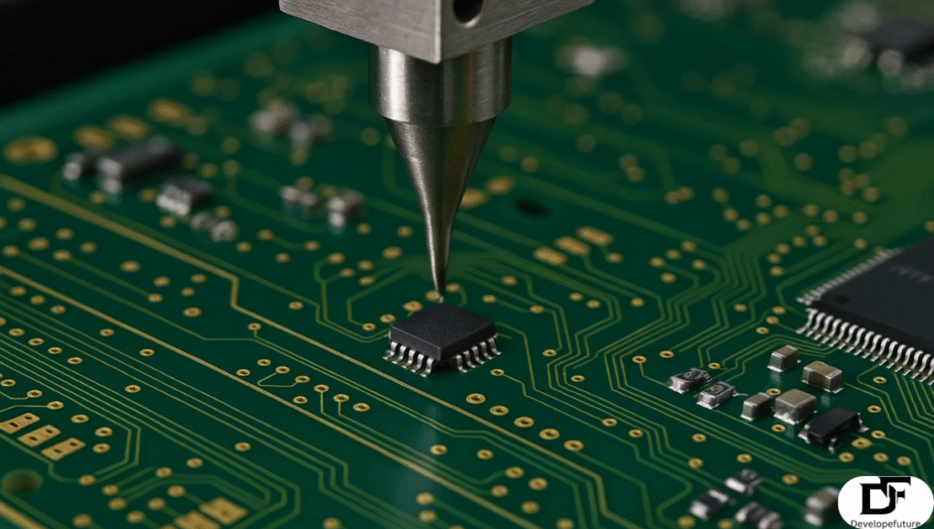
The process begins with applying solder paste onto pads using a stencil. Next, pick-and-place machines position components accurately. The board is then sent through a reflow oven to solder connections. Finally, inspection and testing are carried out to ensure quality.
2) Tools and Methods
Automated machines like pick-and-place systems, reflow ovens, and solder paste printers are essential for mass production. For smaller projects, manual tools like tweezers, magnifying microscopes, and fine-tipped soldering irons are used.
3) Tricks and Difficulties for Troubleshooting
Troubleshooting Surface Mount Technology assemblies requires specialized tools. Such as X-ray inspection systems to detect hidden solder joints, especially for BGAs. Common issues include solder bridging, cold joints, and misaligned components. Experienced technicians rely on thermal profiling and visual inspections to resolve problems effectively.
Managing Board Expansion and Flexure in SMT
PCBs expand when exposed to heat during soldering. This can cause stress on components and lead to cracks or misalignments. Proper material selection and designing boards with thermal expansion in mind cut risks.
Flexure is another concern, especially in thin or large boards. Designers use reinforcement methods like stiffeners, support pins. And proper handling procedures to reduce damage during assembly.
Applications of Surface Mount Technology
SMT is used across industries where compact, reliable, and cost-efficient electronics are required. Consumer electronics like smartphones, tablets, and laptops heavily rely on SMT. Due to their need for high functionality in small form factors.
Industrial applications also enjoy SMT in control systems, robotics, and communication equipment. Automotive electronics, aerospace systems, and medical devices depend on SMT for precision, durability, and performance.
Important Considerations in Surface Mount Technology
When implementing SMT, several factors must be considered. Component availability, board design, manufacturing capabilities, and inspection methods. Cost-effectiveness and scalability are also crucial for mass production.
Environmental considerations are equally important. Lead-free soldering, compliance with RoHS standards. And sustainable manufacturing practices ensure SMT aligns with global regulations and green initiatives.
FAQ’s
What is the main advantage of Surface Mount Technology?
SMT allows miniaturization of devices by enabling smaller components. It’s higher circuit density and faster automated assembly.
Can SMT completely replace through-hole technology?
No, through-hole is still used in applications requiring mechanical strength. Such as connectors and large power components.
What tools are commonly used in SMT assembly?
Key tools include solder paste printers. It’s pick-and-place machines, reflow ovens, microscopes, and X-ray inspection systems.
Is SMT suitable for prototyping?
Yes, but it can be challenging due to the small size of components. Engineers often combine SMT with through-hole for prototyping.
What are the most common SMT component sizes?
Popular sizes include 0603, 0805, and 1206. But ultra-small sizes like 01005 are increasingly used in compact devices.
Conclusion
Surface Mount Technology has revolutionized electronics by allowing miniaturization. Its high-speed assembly, and cost efficiency. While it comes with challenges. Such as rework difficulty and mechanical fragility. Its benefits far outweigh the drawbacks in most applications.
From its development in the 20th century to its dominance in today’s electronics. SMT continues to evolve with new packaging technologies and sustainability practices. Whether in consumer gadgets, industrial systems, or medical devices, SMT ensures electronics remain compact, powerful, and reliable.
As technology progresses, SMT will remain central to innovations in flexible electronics. LoT devices and next-generation smart systems. For engineers, designers, and manufacturers, understanding SMT is not valuable. It’s essential for staying ahead in the ever-evolving electronics industry.